Three Phase Motor Control Circuit Diagram
Introduction To Plc Programming And Implementation 14 Aneka

Variable Frequency Inverter For Speed Control Of A Three Phase Motor

Three Phase Ac Voltage Controller Under Induction Motor Load
Forward reverse motor control diagram for three phase motor for three phase motor forward reverse control circuit.
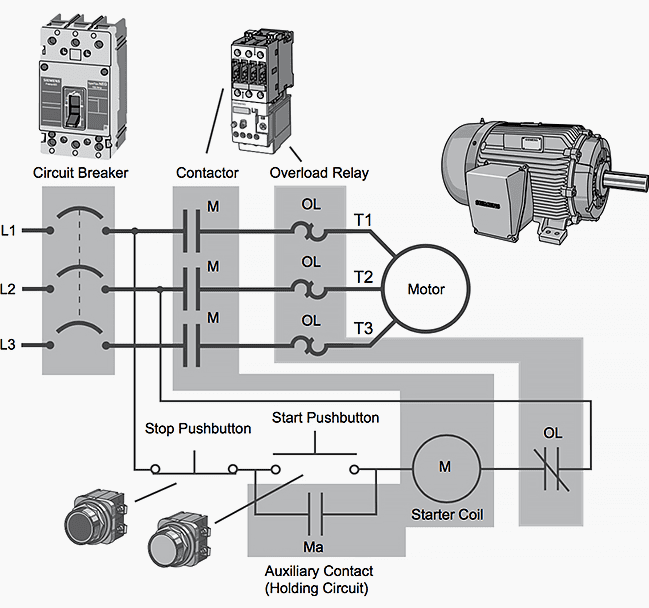
Three phase motor control circuit diagram. Wiring of the direct on line dol motor starter 1 three phase supply 230volt coil see wiring diagram. Control circuits can be divided into two major types. A simple circuit diagram of contactor with three phase motor. Motor contactor magnetic relay and contactor.
Here i showed the forward reverse wiring diagram. Up tp 93 off. You may also read. A simple circuit diagram of contactor with three phase motor.
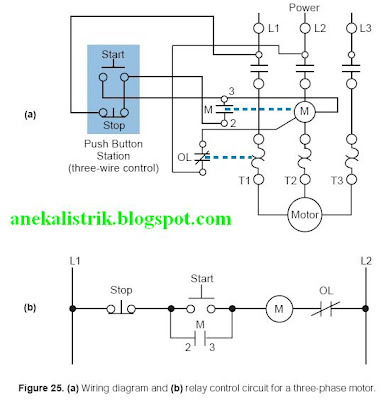
This video walks you through the basic 2 wire and 3 wire control for 3 phase motor controllers. Start stop 3 wire control. Three phase motor power control wiring diagrams 3 phase motor power control wiring diagrams three phase motor connection schematic power and control. I had to do this a few times with floodlights to be used outside.
A two wire control circuit can be a simple switch that makes or breaks connection to a motor figure 18 1. All other control and power connections have to be made by the installer. In the diagram i connect the incoming three phase supply l1 l2 l3 to the mccb circuit breaker molded case circuit breaker. We use 2 magnetic contactors as forward reverse switch.
Two wire control circuits and three wire control circuits. 1 the following links are pre fitted to the starter. This video gives a brief explanation on how a three phase motor control circuit works. Starting a three phase motor.
Next the start pushbuttons are connected in parallel to form an or logic circuit. Contactor design and rating contactor nameplate. A simple circuit diagram of contactor with three phase motor. On abb contactor wiring diagram.
Ladder diagram basics 3 2 wire 3 wire motor control circuit pete vree. The diagram below illustrates the control circuit needed to accomplish the operation. The old post triac based motor speed control if we avoid the pwm control section and power circuit use for just on and off for a low voltage three phase induction motor 100 volt to 150 volt frequently with help of a on off sensorin 100 or more voltagemotor too hot after some time runningif apply 50v three phase it will be working finebut in 50 volt it does not work with full speedcan. A good example of this type of control is the single phase manual starter shown in figure 3.
13 17 with a flying lead to be connected to overload terminal 95. This control circuit is a variation of the three wire control circuit.
Basic Plc Program For Control Of A Three Phase Ac Motor
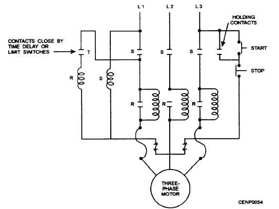
Part Winding Starters
Three Phase Six Step Motor Control Circuit Diagram Composed Of
Three Phase Synchronous Motor Starting Given The F Chegg Com

Gate Drives Circuit Source From Dvb Journal Pic Based Speed

Mr 0958 Phase Motor Control Circuit Diagram Free Download Wiring
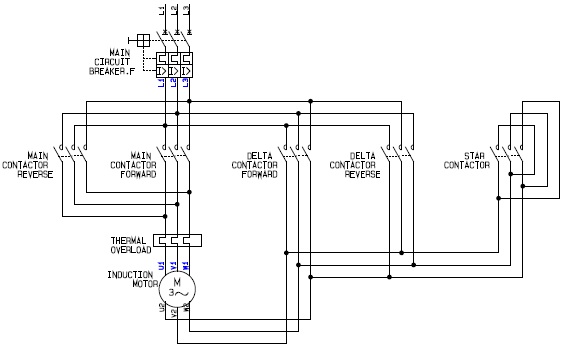
Power Circuit Of A Forward Reverse Star Wye Delta Motor Controller

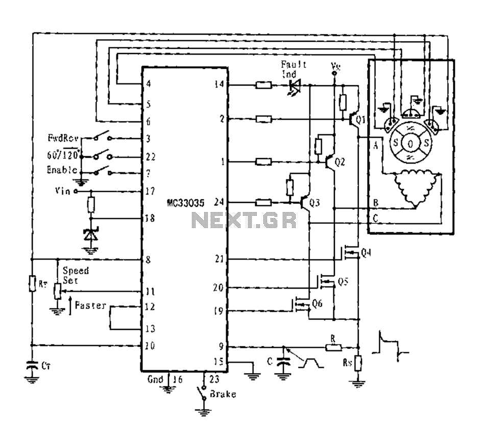
Controlling Sensorless Bldc Motors Via Back Emf Digikey

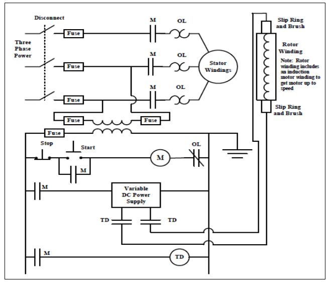
Static Reversing The Three Phase Induction Motor
