3 Phase Converter Wiring
Rolling Out A Slick Rotary Phase Converter Hackaday

Rotary Phase Converter Wiring Diagram Crayonbox Con Imagenes

3 Phase Rotary Converter Wiring Diagram Picture Diagram Base
All power to and from the converter is hard wired meaning no electrical sockets the three phase converter will come with a wiring schematic for properly connecting the black red blue and neutral white lines to the junction box.

3 phase converter wiring. Collection of 3 phase rotary converter wiring diagram. Jeremy fielding 261488 views. 3 phase converter wiring i have a 5hp 3 phase converter that was wired in professionally a few years ago. In this video we show the basic installation techniques of the american rotary phase converter panel.
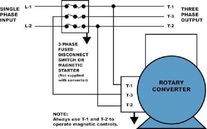
It reveals the elements of the circuit as streamlined forms and also the power as well as signal connections between the devices. Contactor c1 has replaced the drum switch and contactor c2 has replaced the momentary pushbutton for connecting the starting capacitor between l2 and l3. I now have a second machine i want to wire into this converter. Phase converter installation admin 2019 10 23t142252 0500 see how napcco design features make installation of pro line rotary phase converters easy.
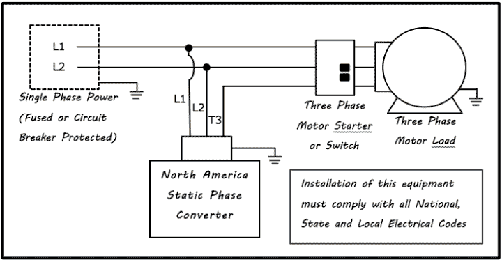
Three ways to run a three phase motor on single phase and the pros and cons of each method 065 duration. Above is the field or power wiring diagram. If you look closely you will see all the basic elements from the very simple static phase converter diagram shown earlier. I do not plan on running the machines at the same time so no worry there.
So they are looking for a static or digital converter replacement 230v to 400v. 3 phase static converter wiring diagram phase. A wiring diagram is a streamlined standard photographic depiction of an electric circuit. It shows the elements of the circuit as simplified shapes and the power and also signal connections between the tools.
A wiring diagram is a streamlined standard photographic depiction of an electrical circuit. The converter is a rotary type quite noisy and recently has been prone to breaking down three times so far this year. Collection of american rotary phase converter wiring diagram. The existing rotary converter is rated at 6kw.
The converter is a machine about the size of a 10 gallon water cooler. Removable backplate large wiring compartment well marked oversized distribution blocks and conveniently located knockouts on all four sides of the control panel simplify installation of pro line rotary phase converters. We have collected lots of images ideally this image is useful for you as well as aid you in finding the response you are seeking.

Three Phase Converter Capacitor Switching Electrical
3 Phase Converter Wiring Diagram Three Phase Converter Wiring

3 Phase Rotary Converter Wiring Diagram Free Picture And With

How To Build A Rotary Phase Converter Youtube
Running A Three Phase Electric Motors On Single Phase Power
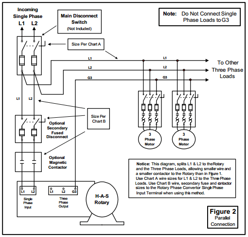
How To Install H A S Rotary Phase Conversion System
How Does Static Work Static Phase Converter Napcco

Rotary Converter

Pam 300hd
