3 Phase Converter Wiring Diagram

Ronk Wiring Diagram Wiring Diagrams Resources

Wy 2511 To Frequency Converter Circuit Diagram 3 Electronic

Cn 6355 Converter To 220v 3 Phase Wiring Diagram Wiring Diagram
Jeremy fielding 261488 views.
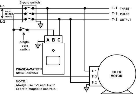
3 phase converter wiring diagram. Collection of american rotary phase converter wiring diagram. L1 l2 3 phase idler motor l1 l2 t1 t2. Our three phase converters are ac single to three phase 208v 220v 240v 440v 460v and 480v converters. It reveals the elements of the circuit as streamlined forms and also the power as well as signal connections between the devices.
If you need a different configuration just let us know. Phase converter installation admin 2019 10 23t142252 0500 see how napcco design features make installation of pro line rotary phase converters easy. See page 5 for specs. 3 phase converter wiring diagram welcome to my web site this article will review regarding 3 phase converter wiring diagram.
All wiring must be done by a licensed electrician. Check phase alignment before adding additional phase converters to circuit. Always have phase converter on before starting any 3 phase load. A wiring diagram is a streamlined standard photographic depiction of an electrical circuit.
Above is the field or power wiring diagram. Removable backplate large wiring compartment well marked oversized distribution blocks and conveniently located knockouts on all four sides of the control panel simplify installation of pro line rotary phase converters. Three ways to run a three phase motor on single phase and the pros and cons of each method 065 duration. A wiring diagram is a simplified traditional pictorial representation of an electrical circuit.
A wiring diagram is a streamlined standard photographic depiction of an electric circuit. Our phase converters are built to last using the highest quality standards and only the highest quality components. It reveals the elements of the circuit as simplified forms and the power and also signal links in between the gadgets. 3 phase static converter wiring diagram phase.
Collection of rotary phase converter wiring diagram. It shows the elements of the circuit as simplified shapes and the power and also signal connections between the tools. Collection of 3 phase rotary converter wiring diagram. We have collected lots of images ideally this image is useful for you as well as aid you in finding the response you are seeking.
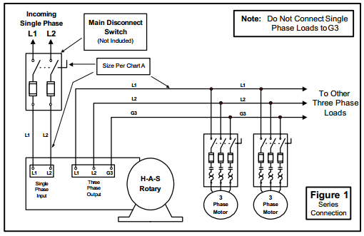
How To Install H A S Rotary Phase Conversion System

Figure 1 From Startup Procedure For Three Phase Three Wire
Phaseconverter
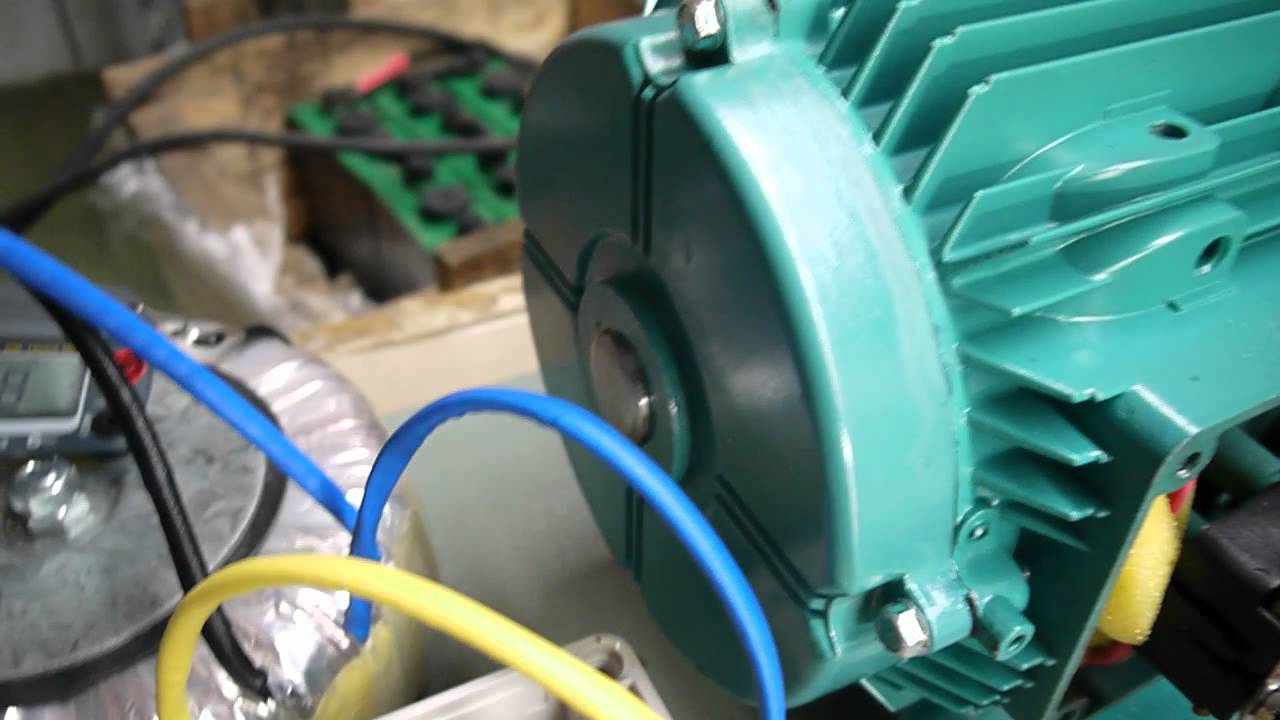
Single To Three 3 Phase Converter Youtube

Practical Machinist Largest Manufacturing Technology Forum On
What Is The Circuit Diagram For A Phase Converter Single Phase To

Phase Rotary Converter Auto Electrical Wiring Diagram

Phase Converter Open Electrical

0f2 3 Phase To Single Wiring Diagram Wiring Library
