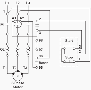
3 Phase Motor Starter Control Circuit
I describe each of the components involved such as the motor starter overload start pushbutton stop pushbutton and control power and.

3 phase motor starter control circuit. Star delta starter y d is a common type of three phase 3 phase induction motor starters generally used in low starting torque motors. This is a 3 phase motor control circuit. Assortment of 3 phase motor starter wiring diagram pdf. Star delta y d 3 phase motor starting method by automatic star delta starter with timer.
A three phase motors large size and high starting torque usually limit its use to industrial settings. Three phase motor power control wiring diagrams three phase motor connection schematic power and control wiring installation diagrams. This is real world 3 phase control circuit wiring. Fourth is the relay switch to operate the relay.
In this tutorial we will show the star delta y d 3 phase induction ac motor starting method by automatic star delta starter with timer with schematic power control and wiring diagram as well as how star delta starter works and their applications with advantages and disadvantages. The second one is the overload protective device. In this video i will teach you step by step how make wiring for 3 phase motor control circuit by using magnetic contactor and thermal overload relay. The motors starter wires directly to the motors wire terminals.
In this video i demonstrate a 3 wire startstop circuit. It shows the parts of the circuit as simplified shapes and also the power and also signal links in between the tools. To use three phase electricity a motor needs windings spaced 120 degrees apart. Motor starters are types switches either electromechanical or solid state that are designed to start and stop the motors by providing the necessary power to the motor and preventing the motor to draw excess current.
The first one is contractor switcher. A wiring diagram is a streamlined conventional photographic representation of an electrical circuit. In this method the motor should be connected in delta for the normal runfor starting star connection used for normal run delta connection used in the motor windingswhen the stator winding is star connected the voltage over each phase in the motor will be reduced by a factor one by 3 of that would be for delta connected windingsthe starting torque will be 13 times that it will be for. Lets first we look at the components of the 3 phase motor.


