3 Phase Motor Contactor Control Circuit

Star Delta Starter Electrical Notes Articles
Devices Symbols And Circuits Reading And Understanding
Single Phase Motor Wiring Diagram
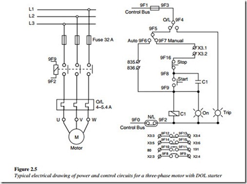
A simple circuit diagram of contactor with three phase motor.

3 phase motor contactor control circuit. The auxiliary contact is often used in a relay logic circuit or for some other part of the motor control scheme typically switching 120 volt ac power instead of the motor voltage. This is real world 3 phase control circuit wiring. Three phase 480 volt ac power comes in to the three normally open contacts at the top of the contactor via screw terminals. This video gives a brief explanation on how a three phase motor control circuit works.
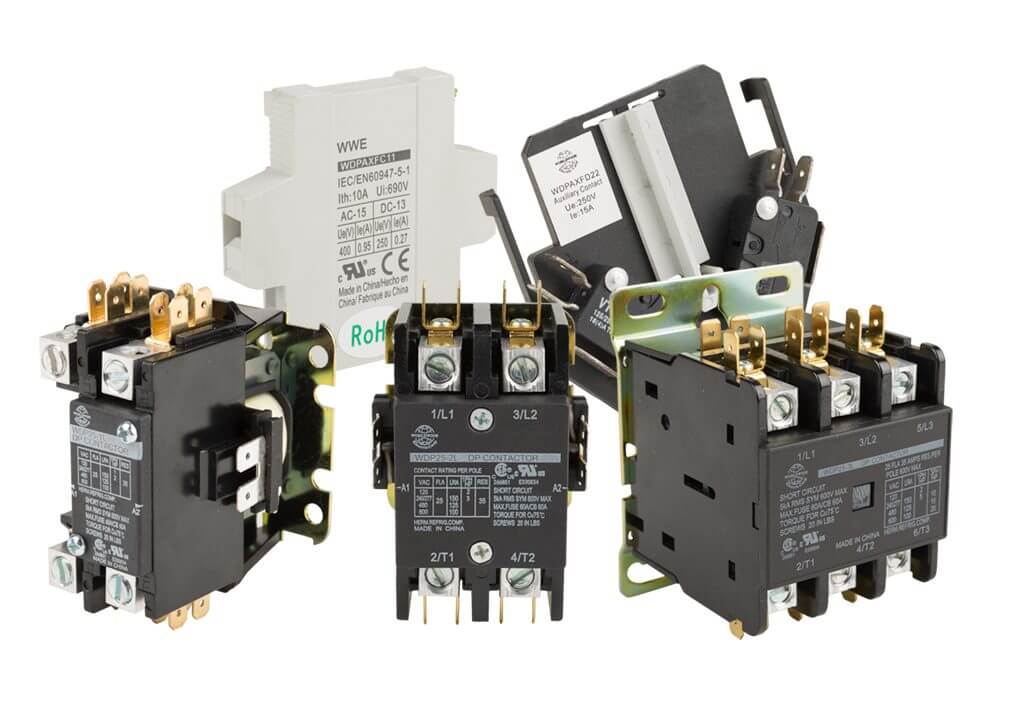
One contactor may have several auxiliary contacts either normally open or normally closed if required. These motors run on a 400v 3 phase supply and can run using less current than an equivalent single phase motor. In this video i will teach you step by step how make wiring for 3 phase motor control circuit by using magnetic contactor and thermal overload relay. Contactor design and rating contactor nameplate.
Contactor wiring with complete explanation. In 3 power system we use some devices between induction motor and supply which are a cb circuit breaker mc magnetic cont actor or motor stater ol overload relay and nc no push button switches for onoff and reset. How to do contactor wiring for 3 phase induction motor with 3 pole circuit breaker overload relay nonc push button switches in this tutorial post i will tell you about motor contactor wiring and its diagram. Start stop 3 wire control.
A wiring diagram is a simplified conventional. Starting a three phase motor. These motors are connected directly to either a 3 phase switch or a contactor as a method of control. How to wire a contactor and.
Shown here is a contactor for a three phase electric motor installed on a panel as part of an electrical control system at a municipal water treatment plant. The main contactor coil gets the phase line l1 through the control circuit only when all the contacts are closed. Contactor for a three phase electric motor installed on a panel as part of an electrical control system. In this case when the start pushbutton is pressed the control circuit is closed and the main contactor is energized.
Examine this three phase motor control circuit where fuses protect against overcurrent and a three pole relay called a contactor turns power on and off to the motor. After years of faithful service one day this motor refuses to start.
What Is A Contactor Library Automationdirect Com
Motor Control Circuit

3 Phase Motor Control Wiring Tutorial Rig Electrician Training

Three Phase Circuit Breaker Wiring Diagram Diagram Base Website

Motor Control Circuits Types Electrical Industrial

How A 3 Phase Motor Control Circuit Works Youtube
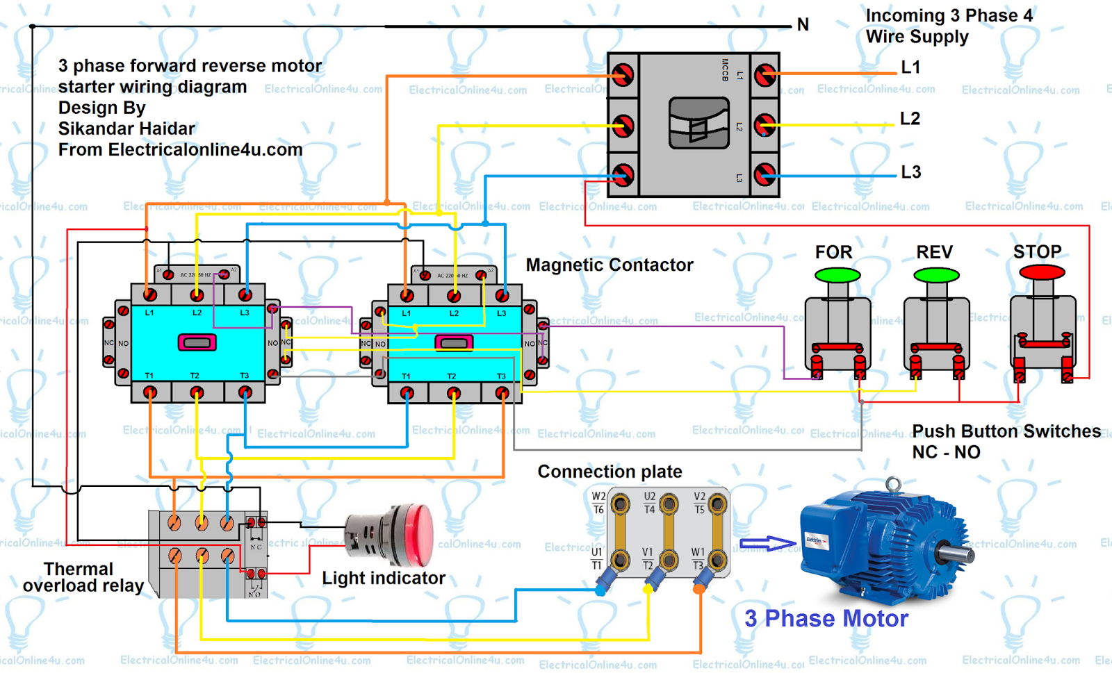
Forward Reverse Motor Control Diagram For 3 Phase Motor
Contactors And Control Circuits

Industrial Control Basics Part 3 Starters C3controls
